Wireless microphones are prone to interference, noise, dropouts, and many other RF problems. These problems can be disastrous for both live productions and installed systems. Malfunctions lasting even a fraction of a second can throw off presentations and performances, driving technical crews, event coordinators, and audiences crazy (not to mention performers and speakers).
Everyone who has worked with wireless audio systems can recall a time when a wireless mic suffered static or intermittent dropouts during a live event. But there are ways to limit or eliminate potential issues. Below are the three most common problems, along with a few basic techniques to solve them.
Multi-Path Interference
Multi-path interference occurs when an RF signal arrives at the receiver's antenna via a straight-line direct path, and also along longer reflected paths. These multiple incidents of the same signal therefore arrive at the antenna at slightly different times.
This phenomenon might be familiar as the visual “ghosts” from back in the analog TV days, or as “picket fencing” when listening to FM on a car radio while driving around a city’s downtown. Radio waves always travel as straight lines, but they can encounter surfaces that reflect or absorb them. Reflected signals arrive at the antenna delayed in phase from the direct signal.
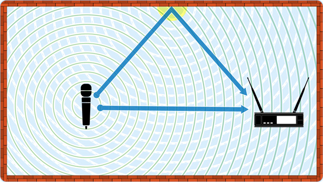
The sum of these reflected signals at the antenna may be of enough phase lag, magnitude, and polarization to partially or even substantially cancel the direct signal, creating dropouts and dead spots for wireless microphones. It's a common problem for wireless microphone systems indoors, where there are a multitude of opportunities for RF to reflect off surfaces.
Multi-path is particularly problematic for microphones since the transmitters are frequently in motion and changing angles. It is best practice to diagnose a performance space for multi-path before showtime by simulating the motion of the talent—literally walking around the entire performance area with a mic while monitoring the RF signal level and audio at the receiver.
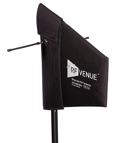
Usually, reducing multi-path interference is straightforward. The diversity receiver was designed to prevent dropouts caused by multi-path, and virtually all professional mic systems use this scheme today. Diversity reception uses two antennas (traditionally spaced wide apart) that see two different perspectives of the RF signal instead of one. Diversity receivers employ a switching function to discriminate between the relative strength of the two signals. The statistical chance that a multi-path null will simultaneously develop at both antennas is very low, and the receiver automatically chooses the strongest signal.
If using the whip antennas included with receivers and multi-path interference is encountered, the first thing to do is to relocate the receivers—or better yet, install a good remote antenna system. Employing a polarization diversity antenna such as RF Venue's Diversity Fin or Diversity Architectural (housing two physically collocated antenna elements with one receiving vertically polarized signals and the other receiving horizontally polarized signals) will eliminate cross-polarization dropouts and provide the receiver with an improved signal on both receiver antenna inputs (both branches of the diversity switching function). This allows receivers to maintain quality reception without all the switching and signal dropouts.
Noise Floor and Interference
It's important to understand that all environments are a soup of radio waves. The biggest “offenders” are broadcast television signals, found in large and small population centers everywhere across the country. They are licensed by the FCC to use 6 MHz-wide slices of the UHF spectrum, so a wireless audio user needs to dodge these signals first. Cellular phone and wireless broadband services are also primary users of RF spectrum that can impact wireless audio devices.
[RF Venue Wireless Essentials Power Austin Stone Church]
Most of the other unwanted energy is caused by electronic devices emitting stray (unintended) RF. Those can be computers, video walls, LED lighting, power supplies, motors—just about any powered digital or switching device. RF noise is present even in the most remote desert, caused by cosmic radiation and natural radiation generated by the earth. Worse yet, noise is often intermittent, present during show time but gone the next day.
An RF system like a wireless microphone needs a sufficient signal-to-noise ratio (aka carrier-to-noise ratio) to maintain performance. Isolating wireless mic signals from the noise environment helps. In general, the closer the wireless receivers (or remote antennas) are to the wireless mics the better, because it results in a stronger signal at the receiver without increasing the noise floor.
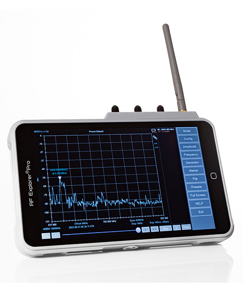
We would hope that the ambient RF noise floor at a venue is about -80 dBm or lower, but with planning and best practices, we can usually work noise floors of -70 dBm and higher successfully. RF spectrum analyzers and wireless microphone management software that include spectrum analysis capabilities are the best tools for examining the RF environment of a venue.
Vertical whip antennas are omnidirectional in the horizontal plane, so they typically pick up noise from all 360 degrees around them. “Paddle” or "shark fin" antennas typically have a horizontal pattern about 120 degrees wide, so they attenuate signals not in their pickup direction, but even they might not sufficiently isolate the desired signals in a high-noise area.
Specialized antennas and signal management techniques can be the difference between success and failure. Selecting a less sensitive, local field antenna like the RF Venue Spotlight may help isolate received signals from the noise, allowing a wireless system to work even the most crowded RF environments. Plus, adding a pair of appropriate bandpass filters can typically reduce the noise floor by 4-6 dB. Using top-quality, 100% shielded coax cables can reduce the ingress of stray RF into a system as well.
Frequency Coordination
Frequency coordination is essential in managing wireless systems. The goal is to avoid not only third-party transmitters but also the harmful effects of intermodulation distortion (IMD).
IMD is the result of two or more signals passing through a nonlinear circuit, such as a diode or an overdriven RF amplifier, and manifests as ghost signals from wireless mic bodypack or handheld transmitters. These appear at predictable sum-and-difference frequencies in the RF spectrum. If these ghosts are too close to one of the frequencies used by a microphone, audible distortion can result.
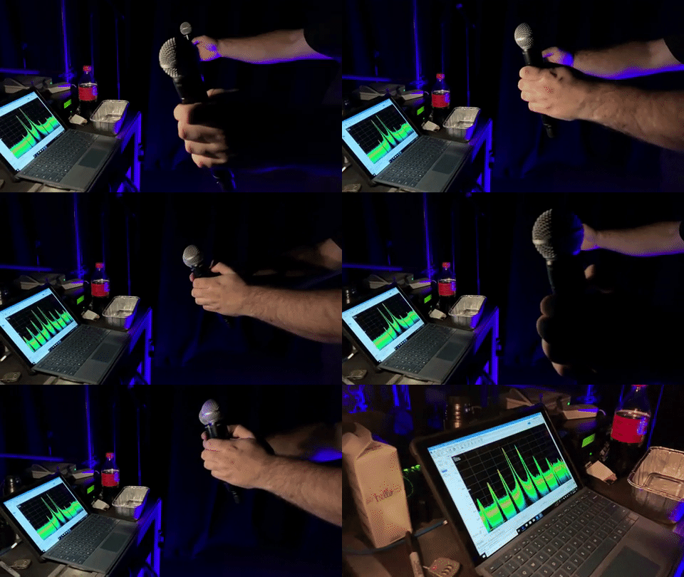
When two wireless mics are brought into close proximity, IMD can occur based on the frequencies in use. By carefully selecting frequencies, IMD can be forced to occur only at frequencies that we don’t care about, avoiding interference events altogether.
[The Integration Guide to Dante-Enabled AV]
This is most commonly achieved through determining an "intermod-free" set of frequencies, which can be calculated using various software tools like Audio-Technica’s Wireless Manager, Professional Wireless Systems’ IAS, RF Venue's Wireless System Builder, Sennheiser’s Wireless System Manager, or Shure's Wireless Workbench. Some receivers have this built-in capability as well. Getting an elegant solution from these tools requires providing them with the best possible data, so scan a frequency range at least 50 MHz above and below any frequencies that a system may be tuned to.
The importance of frequency coordination in today's scene cannot be understated, as the wireless landscape continues to evolve with more and more devices competing for less available spectrum. Choosing the right antennas for the application and maintaining transmitter/receiver line of sight in combination with frequency coordination can prevent dropouts.
